
TL;DR: Capture the CC line signals –> export the trace to a data file –> convert the analog signals to digital signals –> import the converted file into sigrok –> use sigrok’s PD decoder to decode.
Hi PD fans! Today I’m gonna tell you guys how to manually (maybe) “sniff” the source capability of a PD power source and also monitor the negotiations between the source and sink. Let’s go!
The basic process is to capture the CC line signals –> export the trace to a data file –> convert the analog signals to digital signals –> import the converted file into sigrok –> use sigrok’s PD decoder to decode.
Things you might need:
- USB type-C test boards or/and USB type-C cables
- USB C to A adapter or 5.1K ohm resistor
- Oscilloscope or logic analyzer with adjustable threshold voltage, and both should be able to export data files
Of course you can use any method you prefer. I use USB type-C test boards + USB C to A adapter + Oscilloscope to achieve. Here’s how I do.
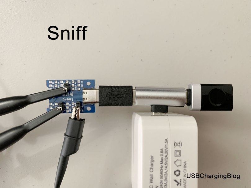
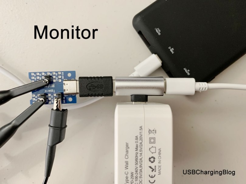
First, I connect the test board to the PD power source with a USB C splitter. Next, attach probe tips to CC1 and CC2 pins/lines and attach the ground tip to GND pin/line. Next, attach the USB C to A adapter to the splitter if you only want to sniff the source cap, but I will do both so connect the splitter to a PD device via a USB C cable.
And then I set the samplerate to 2.4Msps (actually 1Msps is good enough) and let the oscilloscope start recording, and then I power on the PD power supply immediately after that. When I finish recording, I export the voltage signals to a txt file which can be downloaded here CC1_Signal_Capture_Optimized-USBChargingBlog.txt. The file has been optimized to be compact.
Then I use Google Sheets to do the conversion. ARRAYFORMULA is the only function used, simple but worked. I have shared the spreadsheet. https://docs.google.com/spreadsheets/d/1ozkdXvJXXIjRttk5Xde2YyXq2Q6NuvYsr4SqxQnHyjc/edit?usp=sharing
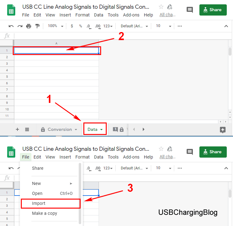
1. Go to the Data sheet, delete the content (if any), click on the A1 cell, and then click on File in menu, and then select Import.
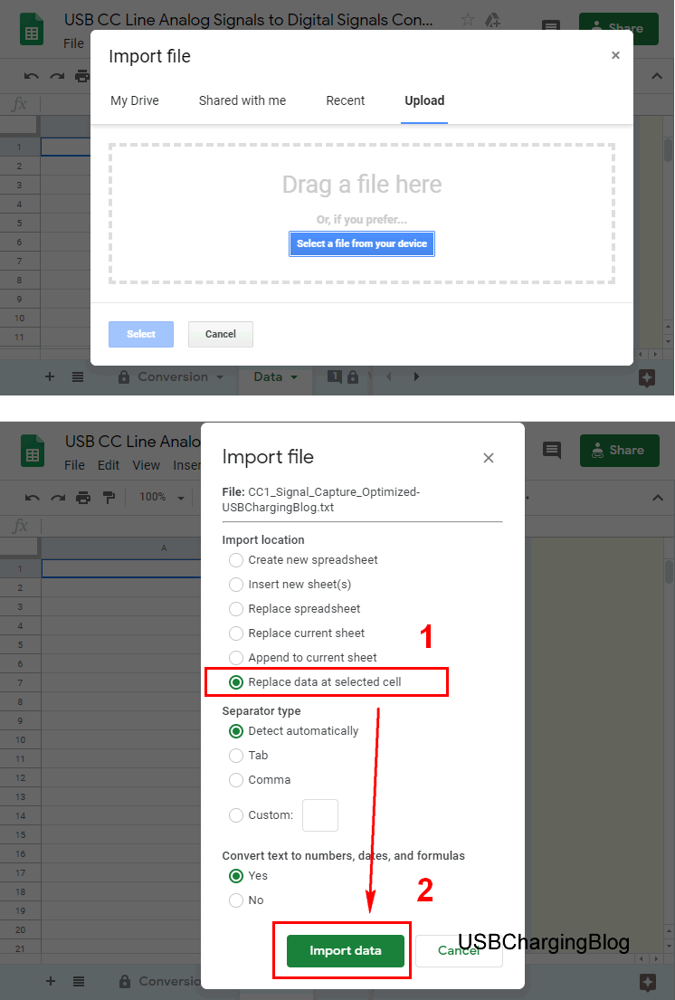
2. Upload the CC1_Signal_Capture_Optimized-USBChargingBlog.txt file, and then select Replace data at selected cell, and then click Import data.
3. Optional. Go to the Variables sheet and change the Threshold Voltage if necessary.
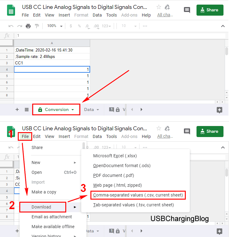
4. Go to the Conversion sheet, and the conversion result will be shown here. Click on File in menu, and then select Comma-separated values (.csv, current sheet) in the sub-menu under Download to export the file.
You will get a file similar to this USB CC Line Analog Signals to Digital Signals Converter – Conversion.csv.
The next thing we need is sigrok. The sigrok is a Free/Open-Source signal analysis software suite. You may download it here: https://sigrok.org/wiki/Downloads. Download the Nightly build of PulseView because the PD decoder will perform better than a stable release.
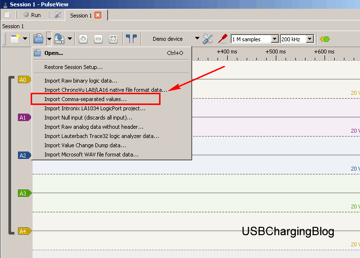
Run PulseView, click Import Comma-separated values…, and open the csv file just exported.
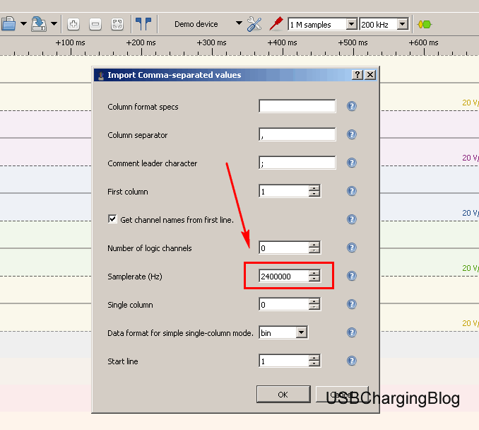
I input 2400000 for Samplerate (Hz) since the samplerate of my capture is 2.4Msps.
Finally add the USB PD decoder to the trace.
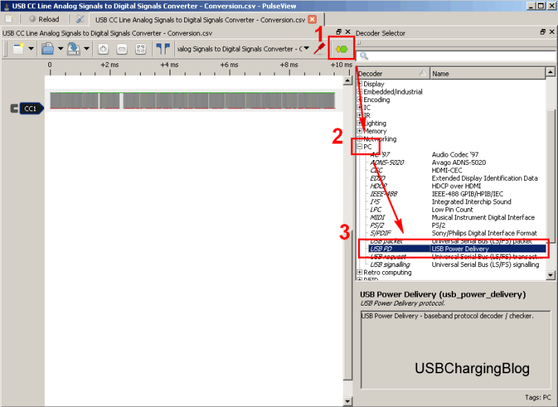
Beautiful!


Now we can see what happened between the source and sink.

And here’s what happened:
SRC: Can I see your ID?
SNK: …
SRC: Can I see your ID?
SNK: …
SRC: Did you hear me?
SNK: Yes.
SRC: Can I see your ID?
SNK: …
Interesting! XD
You can save some work if your device is supported by sigrok.
Resources
The files I used in this article
- CC line signals capture CC1_Signal_Capture_Optimized-USBChargingBlog.txt
- Google spreadsheet https://docs.google.com/spreadsheets/d/1ozkdXvJXXIjRttk5Xde2YyXq2Q6NuvYsr4SqxQnHyjc/edit?usp=sharing
- Digital signals file USB CC Line Analog Signals to Digital Signals Converter – Conversion.csv

Great article! I figured that something like this was probably possible, but I was afraid to try because I figured I would probably get something subtly wrong. Sigrok / Pulseview decoders seem to give very little feedback if things aren’t right – they either decode perfectly or not at all.
My current way of analyzing what PD profiles a power supply supports is plugging in a ZY12PDN and pressing the button to toggle the voltages. I’d like to understand a bit more than that. Do you think sigrok with a simple 1MSPS logic analyzer would be a good way to watch PD negotiations?
The most interesting PD behavior I’ve seen was a cigarette lighter adaptor that claims to support 20v@1.5A, but it was a buck-only converter. I hooked it up to lab power supply and my ZY12PDN to see what voltages it would put out. If the input voltage was above ~20v, it would offer 5v, 9v, 12v, 15v or 20v.
The interesting things it did: It was smart enough to know that it couldn’t boost, so it would not offer higher voltages than it could provide. If the input voltage was 16v, it would offer everything but 20v. If the input voltage was 11v, it would only offer 5v and 9v.
Using the ZY12PDN, whenever it crossed a threshold that would eliminate or add a new voltage, the ZY12PDN would drop down to 5v. I don’t know if that’s the ZY12PDN being weird or not – whether another device would, say, keep getting 9v as the input voltage varied from 15 to 20v. The only 9v devices I have are expensive Apple products, so I am a bit nervous.
LikeLike
– Do you think sigrok with a simple 1MSPS logic analyzer would be a good way to watch PD negotiations?
A simple 1MSPS logic analyzer won’t capture a PD trace correctly. Therefore, if you would like to use sigrok with a logic analyzer, you would want to have a logic analyzer with adjustable threshold voltage below 1V. With that, you could watch PD negotiations including the Physical Layer and Protocol Layer. Although it can only decode some basic messages, I guess it’s enough for many people. For me, when I pay attention to the entire process of PD negotiations including time, I will use the sigrok PD decoder I developed, and when I only pay attention to PD messages, I will use my PD decoder.
– The interesting things it did: It was smart enough to know that it couldn’t boost, so it would not offer higher voltages than it could provide. If the input voltage was 16v, it would offer everything but 20v. If the input voltage was 11v, it would only offer 5v and 9v.
Your car charger was good and doing right things. That’s how a buck-only PD car charger should work. It’s much better than advertising a 20V PDO but rejecting requests.
– Using the ZY12PDN, whenever it crossed a threshold that would eliminate or add a new voltage, the ZY12PDN would drop down to 5v. I don’t know if that’s the ZY12PDN being weird or not – whether another device would, say, keep getting 9v as the input voltage varied from 15 to 20v. The only 9v devices I have are expensive Apple products, so I am a bit nervous.
This behavior reflects the algorithm of ZY12PDN. I guess the algorithm is that once it receives a Src_caps message, it will request the first object, which is the 5V Fixed Supply PDO, by default. Without analysis, it is difficult to determine whether your cigarette lighter adapter is totally compatible with Apple products. That’s because PD negotiations of Apple products are often not so straightforward and some violations of PD specs may occur from time to time. However, in most cases, it should work, but maybe it cannot fully satisfy Apple products.
LikeLike